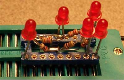
This PDF schematic shows diagrams for testing all the PIC Programmers. User instructions are enclosed.
Notice that the schotty diode allows the DIY Programmer to feed its VCC without its VCC being shorted to the PIC's normal power supply. A tiny DIP switch will also work in place of the diode. NOTE: the diode is very convenient when developing the code, but it drops about 100mV of the VCC provided (but was never an issue in my designs. Simply do NOT power the PIC while programming it.

The reason for this schematic is to clarify how ICSP is driven by a DIY programmer.
The PIC programmer itself is designed to provide only enough VPP and VDD to program the device, nothing else. With the schottky diode, the VDD load of the product itself is ignored by the programmer while programming. The cap across the chip is very important, and can be as low as 0.01uF and as high as 0.1uF - but it can't be higher, otherwise the rise time needed to enter programming mode cannot be achieved.
The other reason is the way PICs must enter programming mode. Some need to have VCC applied first, while others need to have VPP applied first. That two-step process, together with PGD and PGC at GND, causes the PIC to enter programming mode.
Bob Axtell

This
PDF schematic shows diagrams for testing all the PIC Programmers. User instructions
are enclosed.
Not stated is the obvious: if NONE of the leds wink, there is a communication problem to the programmer, USB drivers, cable etc, although the internal PIC chip could also be inserted backwards or be otherwise defective.
Bob Axtell